FFT
Use the FFT command to edit a grayscale image in its spectral form. FFT editing is useful for removing periodic noise from an image. This type of noise can be very difficult to remove using spatial filters, but tends to generate isolated energy spikes that are easily de-emphasized or removed in the FFT spectrum.
The following general steps are required to perform an FFT transformation:
-
Open the image that has periodic noise that you want to characterize or remove.
-
Use the Forward tool to display the image as an energy spectrum.
-
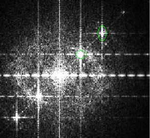
Edit the spectrum to enhance, attenuate or eliminate certain characteristics. This is done by drawing an ROI around a particular group of frequencies that identify the periodic noise, and then clicking the Apply button on the FFT Filter dialog box. What is selected in the Type pull-down list box determines whether the spectrum spikes are enhanced, attenuated, or eliminated.
-
Perform an FFTInverse transformation to write the edited data back to the original window, or to a new window. To do this, click the Inverse button on the FFT Filter dialog.
Forward Button
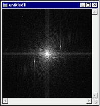
Click this button to generate a transformation of the active ROI or image. The Forward button will produce a new window containing a representation of the FFT data for the image.
If an AOI is active when the Forward button is clicked, just the pixels within the AOI will be transformed. The Forward button will only be enabled when an image is in the active window. If the FFT window is active, this button will be dimmed.
When you click the Forward button, the FFT dialog box is displayed.
FFT Filter
The controls in this group allow you to filter the FFT spectrum. To filter the FFT spectrum, you must (1) draw ROIs around the spikes of interest in the FFT image (or use the Detect Spikes tool to automatically select them), (2) select the desired filter options, described below, and (3) click the Apply button.
Symmetric ROI: Check the Symmetric ROI check box if you want the Spike Cut and Spike Boost filters to affect the specified frequencies in both halves of the FFT data set. When the Symmetrical option is set, you will see that the corresponding group of frequencies in the opposite half of the spectrum are also cut/boosted when you perform a Spike filtering operation. If you do not want this to occur, disable the Symmetric ROI option.
Preserve Nil Frequency: Check the Preserve Nil Frequency check box if you want to preserve the average intensity of the image when using a HiPass frequency filter. This check box has no effect with LoPass, Spike-Cut, or Spike-Boost filters.
Hanning: Select this option if you want to attenuate the specified frequencies, rather than setting them to null. Attenuation is performed at the rate specified in the Transition field. If the HiPass or Spike Cut frequency filter has been selected, the Hanning option will attenuate all frequencies within the masking-ROI. If the Low-Pass filter has been selected, the Hanning option will attenuate all frequencies outside the masking-ROI.
Transition: Set this value to specify the rate at which the specified frequencies will be attenuated. The closer the Transition value is to 0, the more the result will resemble the rectangle option (Hanning off, setting the specified frequencies to null).
Boost Scale: This is only used by the Spike Boost filter type (described below). It specified the boost coefficient. The larger the number, the greater the boost.
Type: There are several filter types from which you can choose:
- Low
Pass: Select this filtering option if you want to eliminate
or attenuate the frequencies above a specified range. When you select
the Low Pass option, you must define an AOI around the center of
the spectrum. Adjust the AOI so that it encompasses only the frequencies
you want to remain in the image. Frequencies outside of the AOI will be
eliminated if the Rectangle filtering option is selected, or attenuated
if the Hanning filtering option is selected.
LowPass frequency editing has the same effect as applying a LowPass spatial filter in that it softens the image. The advantage of using the Low Pass frequency filter over the Low Pass spatial filter is its flexibility and ease of use. Experimenting with the frequency spectrum is usually easier to do than developing the exact spatial kernel configuration to produce the desired effect. - Hi
Pass: Select this filtering option if you want to eliminate
or attenuate the frequencies below a specified range. When you select
the Hi Pass option, you must define an AOI around the center of
the spectrum. Adjust the AOI so that it encompasses the frequencies you
want to remove from the image. Frequencies inside of the AOI will be eliminated
if the Rectangle filtering option is selected, or attenuated if
the Hanning filtering option is selected.
Hi Pass frequency editing has the same effect as applying a Hi Pass spatial filter in that it produces an image with only high contrast elements. The advantage of using the Hi Pass frequency filter over the Hi Pass spatial filter is its flexibility and ease-of-use. Experimenting with the frequency spectrum is usually easier to do than finding the exact spatial kernel configuration to produce the desired effect. - Spike Cut: Select this option if you want to eliminate or attenuate just a certain frequency, or group of frequencies, in an image. When you select the Spike Cut option, you must define an AOI around the group of frequencies you want to cut. Adjust the AOI so that it encompasses just the frequencies you want to remove from the image. Frequencies inside of the AOI will be eliminated if the Rectangle filtering option is selected, or attenuated if the Hanning filtering option is selected.
- Spike
Boost: Select this option if you want to accentuate a certain
frequency, or group of frequencies, in an image. When you select the Spike
Boost option, you must define an AOI around the group of frequencies
you want to enhance. Adjust the AOI so it surrounds just those frequencies
that you want to boost. The energy of the frequencies inside the AOI will
be increased up to twice their value.
Detect Spikes: Click this button to have Image-Pro automatically detect the spikes in the FFT image. Automatically detected spikes will be selected with ROIs when this tool is clicked. Two controls are available to adjust the auto-detection feature:
- Number of Spikes: Specifies the maximum number of spikes you want auto-detected.
- Size
Threshold: Specifies how big a peak has to be to be selected by
the auto-detection routine.
Apply:
Click this
button to apply the type of filtration you have selected in the Type control according to the filtration
settings you have selected.
Display
Show FFT Pattern on Source Image: Select this option to show the FFT pattern on the source image when you are drawing ROIs around peaks in the FFT image. When selected, the frequency period, distance and angle corresponding to the cursor position you click on in the FFT image is shown as diagonal lines in the source image. In order to see this effect, be sure your source image is visible on your desktop, then in the inverted image create an AOI that surrounds the area that you want to alter. The source image reflects where the changes will occur.
Inverse: Click this button to generate an inverse transformation of the active FFT window. The Inverse button will write the FFT data back to the source image. For example, if spikes were deleted from the FFT image, the fixed pattern noise they represent will be removed from the source image.
FFT Pull-Down Menu Options
The following options are available by clicking the Forward tool drop-down arrow:
Forward: See Forward Button above.
Remove Periodic Noise: Click this button to automatically remove periodic noise from the image using FFT filtration. This option uses automatic detection of peaks and the default FFT filtration options to remove the periodic noise.
New Image: When selected, the result of the filter is written to a new image in the application workspace. Otherwise, the result of the filter is written to the source image.
Side by Side: When selected, the application workspace is automatically configured to show the source and FFT images side by side after the FFT image is created.
Activate ROI Tool: When selected the ROI drawing tools are automatically activated after the FFT image is created.
Use Apodization: When active the apodization routine is applied to the source image before creating of FFT transform. The goal of apodization is to decrease the amplitudes of the sidelobes and achieve a clean spectrum of the image.