Relative
The tools in this group allow you to obtain angle and distance measurements that express a relation between two measurement overlays already traced in the image. For example, suppose you have traced two lines in your image using the Line measurement tool -- you can select them both and click on the Angle Between Lines tool to have Image-Pro automatically calculate their angle in relation to each other.
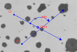
Angle of Lines: This tool allows you to have Image-Pro automatically calculate the angle between any two lines that have been traced in the image. The lines of interest may or may not intersect, and they can have been created by any of the line tools other than the Polyline tool (specifically, the Line, Point-to-Point, or Best-Fit Line tools).
When calculating this measurement, the direction of the lines and the order in which they are drawn is taken into consideration. The arrows at the ends of the top and bottom of the tool indicate the direction of the lines. The shortest angle is created when the lines are drawn in the same direction. The angle is drawn from the second line to the first line.
The angle range is determined by the option in the Angle tool dropdown and can be 0…180, -180…180 (default) or 0…360.
It is computed as the difference between the vector angles (measured counterclockwise from the positive, rightward, horizontal axis) of the first selected line, tail-to-head, minus the second selected line, head-to-tail, limited to +/-180 degrees. The measurement thus depends both on the order in which the lines are selected and the directions in which they are drawn (in an opposite sense).
The arc is drawn from the center of the second line in most cases, unless the center is close to the intersection point. In that case the arc is drawn from the point with fixed offset from the center:
The arc is always drawn from the mid-point of the second selected line to the point where the arc intersects the first selected line or its projections. The arc is drawn in either a clockwise or counterclockwise direction to create an arc that covers an angle equal to the absolute value of the measurement (computed as described above). The arc starts at the midpoint of the second selected line and ends on the first selected line or its projection. The direction that the arc is drawn is not determined by the sine of the measurement value. Rather, it depends on the location of the midpoint of the second selected line relative to the trajectory of the first selected line.
To use this tool:
Click on the first line of interest.
While
holding down the <Ctrl> key, click on the second line of interest.
The Angle of Lines tool becomes activated.
Click
on the Angle of Lines tool.
Distance Between Centers: This tool allows you to have Image-Pro automatically calculate the distance between the centers of any two objects that have been traced in the image.
To use this tool:
Click on the first object of interest.
While holding down the <Ctrl> key, click on the second object of interest.
Click on the Distance Between Centers tool.
Minimum Distance: This tool allows you to have Image-Pro automatically calculate the minimum distance between two objects traced in the image.
To use this tool:
Click on the first object of interest.
While holding down the <Ctrl> key, click on the second object of interest.
Click on the Minimum Distance tool.
Maximum Distance: This tool allows you to have Image-Pro automatically calculate the minimum distance between two objects traced in the image.
To use this tool:
Click on the first object of interest.
While holding down the <Ctrl> key, click on the second object of interest.
Click on the Maximum Distance tool.
First/Center/Last Point: These tools allow you to have Image-Pro automatically place a point feature at the beginning, middle, and end points of an object traced in the image.
To use these tools:
Click on the object of interest.
Click on the First/Center/Last Point tool.
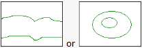
Incremental Distance: This tool allows you to have Image-Pro automatically calculate the thickness distribution between two lines. The lines can be roughly parallel open poly-lines, or they can be closed shapes, one inside the other (like a doughnut).
You can also use the Incremental Distance tool on single region closed polygons of any shape. Click here for more information.
To calculate the thickness distribution between two lines, either roughly parallel or in a doughnut shape:
Click on the first line of interest. This will be considered by Image-Pro the Reference line.
While holding down the <Ctrl> key, click on the second line of interest. This will be considered by Image-Pro the Object line.
Click on the down arrow to the right of the Incremental Distance tool, and define the desire Step Size and Type option.
The options of this dialog are described Incremental Distance Tool Options.
Click on the Incremental Distance tool.
Using the Incremental Distance Tool with Polygons
It is also possible to create incremental distance measurement for a single region object (closed polygon). If the region object contains a hole, incremental distance will be calculated between object outline and the hole (doughnut thickness measurement, as described above). If the object does not contain a hole, incremental distance will be calculated between 2 opposite sides on the region object along the given Angle. The offset of “Step Size” on both sides of the object is used to avoid zero length lines. When Auto angle is on, the angle is calculated automatically.
Grow: Click on this tool to enlarge the selected objects by applying the “Dilate” morphological filter to them. The size of dilation is control by the “Size” control of the Shrink tool (described below).
Shrink: Click this tool to shrink the selected objects by applying the “Erode” morphological filter to them. Click the down arrow next to the Shrink tool to show the “Increment” control. Enter the desired size of erosion/dilation, in pixels, in the Grow/Shrink Increment spin box. Note that this control applies to both the Grow and Shrink tools.
Open: Use this tool to separate neighboring features if they are connected by a narrow path. This tool opens the narrow path by applying a morphological Open operation to the selected regions. Use the Open/Close Size control, accessed by clicking on the arrow next to the Open tool, to specify the size, in pixels, that you want Image-Pro to make the opening. Note that this control applies to both the Open and Close tools.
Close: If there is a narrow pathway separating two regions of the same feature, you can use this tool to close the narrow pathway. Simply select the two regions that you want to merge, and click on the Close tool. It closes the gap between the selected regions by applying a morphological Close operation to them. Use the Open/Close Size control, accessed by clicking on the arrow next to the Open tool (described above), to specify the size, in pixels, that you want Image-Pro to close off the narrow pathway separating the features.
Merge: Clicking the Merge button will combine all selected objects into one, connecting all object by the shortest line that can be drawn from one object to the next. Note, that the Merge function is available only for objects of Region type (polygon, ellipse, circle, count/size objects, and so on).
Incremental Distance Tool Options
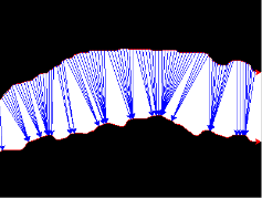
Step Size: When the Incremental Distance tool is selected, it draws a series of lines from the Object line to the Reference line to get many samples of the thickness. For example:
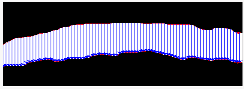
The Step Size control defines how many pixels apart the lines should be spaced on the Object line. For example, if you specify five for Step Size, the thickness sampling lines will be spaced 5 pixels apart for the length of the Object line.
Type: In this control, select the option that describes how you want the thickness sampling lines to be drawn.
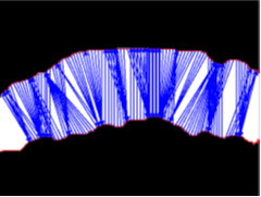
- Shortest – If you select this option, Image-Pro draws the shortest possible thickness sampling lines from the Object line to the Reference line. The starting points along the Object line are equally distributed according to the interval defined by the Step Size control.
- Shortest bi-directional – If you select this option, Image-Pro draws the shortest possible thickness sampling lines from the Object line to the Reference line, and then draws another set of thickness sample lines from the Reference line to the Object line. The starting points along the Object and Reference lines are equally distributed according to the interval defined by the Step Size control.
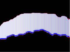
- Equidistant –If you select this option, Image-Pro draws the thickness sampling lines from the Object line to the Reference line and, in this case, the Step Size interval is applied to both lines; each point along the Object line is connected to its corresponding point along the Reference line.
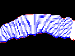
- Directional – If you select this option, Image-Pro draws all parallel thickness sampling lines from the Object line to the Reference line. The starting points along the Object line are equally distributed according to the interval defined by the Step Size control.
Angle: This control is only meaningful if you select “Directional” as the Incremental Distance “Type.” With the Directional type, the orientation of thickness sampling lines is defined by the angle you specify here (in degrees, from the X axis, counterclockwise). When Auto Angle is selected, the angle is calculated automatically based on the object and reference lines.
Hide Base Lines: Use this control to show/hide the base lines.